|
Asynchronous Circuit and System Design Group
|
Asynchronous Open-Source DLX Processor (ASPIDA)
|
Mapping and Place and Route Procedure Summary
|
| |

General Information
The router was instructed to use low skew lines for the signals that
the asynchronous controllers generate for the pipeline flip-flops.
However, this is not possible for the current device (xcs2s200e)
and the router implemented some of the signals using low skew lines and
the rest by trying to adjust the skew locally.
The calibration of the delay elements seemed to demand extensive
floorplanning. The approach we used is summarized below.
Floorplanning
It is a fact that the dominating delay in the delay element is not the
delay
of the LUTs that implement the gates, but rather the routing delay of
the
wires that connect the LUTs. Thus, the need to control the routing
delay
has risen. In order to control the routing delay, floorplanning has
been used extensively. The delay elements have been assigned an area of
the FPGA using the ``RANGE'' constraint. It has been observed that the
larger this area is,
the more unpredictable the delay becomes. In reverse, the use of
``LOC'' constraints
on each gate has resulted in almost a fixed delay. It has to be noted
that
the assigned locations of the gates with the ``LOC'' constraint were in
consecutive
slices making the routing straightforward.
After experimenting with the ``RANGE'' and the ``LOC'' constraints, a
conclusion
has been reached. Taking for granted that the resource usage of the
FPGA is
about 99%, the ``LOC'' constraint seriously hampered the optimization
of
the datapath resulting most of the times in poor timing results. The
``RANGE''
constraint has offered deterministic results for the delay of the delay
elements
and has been proven not to have a negative effect on the overall
performance
of the DLX.
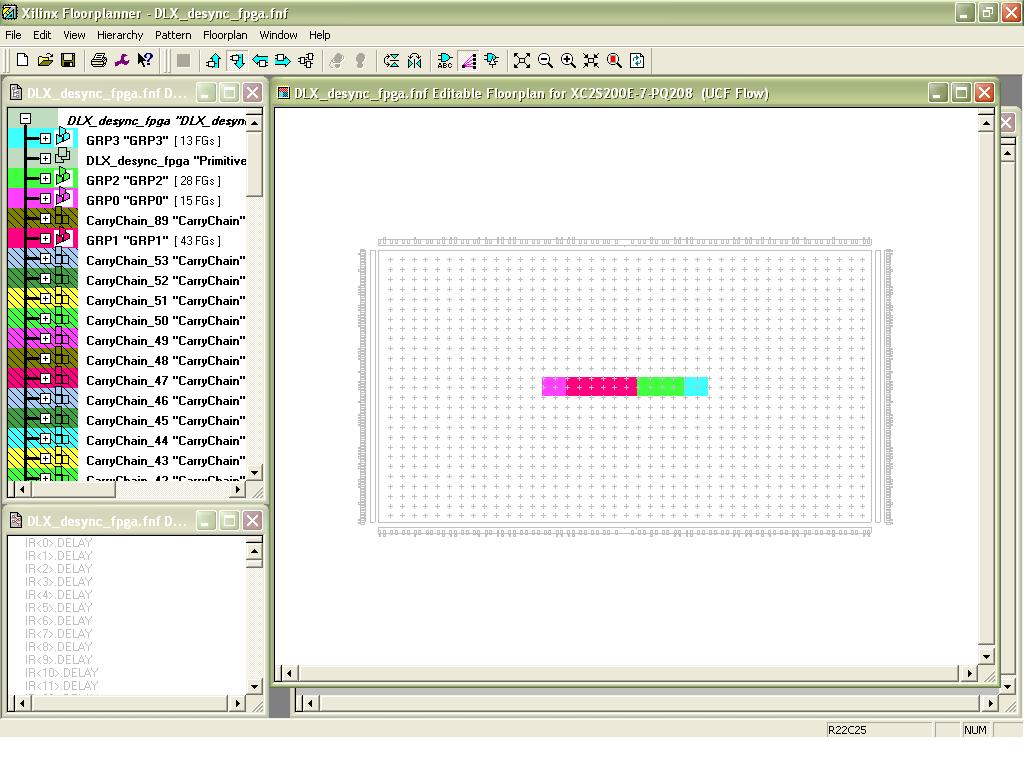
In the picture below, you can see a floorplan grab which shows how the
``RANGE''
constraints for the delay elements have been added to the design.

|
|